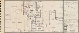
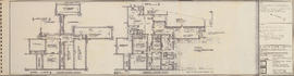
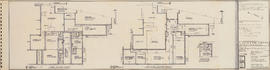
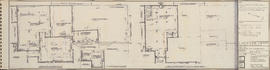
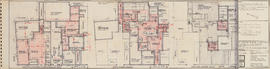
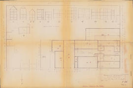
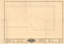
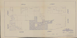
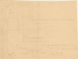
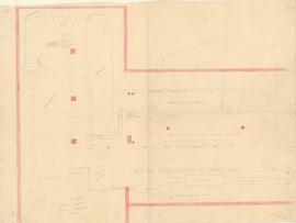
Third & fourth floor plans : Unit C
- MS-4-135, OS Folder 13, Item 4
- Item
- November 1, 1970
Part of Oland and Son fonds
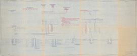
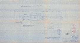
Item is a drawing of floor plans of Unit C of the A. Keith and Son brewery. The drawing shows floor plans of the third and fourth floors of Unit C and some of Unit B. The drawing was originally bound in a booklet with other drawings of the building. The drawing was produced by Hancock Little Calvert Associates.


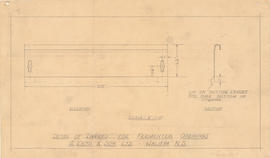
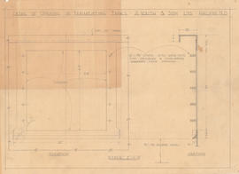
![Fermenter tanks 8'-0" wide x 15'-1" lg. x 8'-6" high : [drawing]](/uploads/r/dalhousie-university-archives/8/a/2/8a2d6ce9e5ae84f395a0dd0158f8d9c81c4fd3a30559953aa9cfbbe09cde8a1f/ms-4-135_os23_003_142.jpg)
![Fermenter tanks 8'-0" wide x 15'-1" lg. x 8'-6" high : [drawing]](/uploads/r/dalhousie-university-archives/7/b/5/7b57e96fe764abb4d543fdcf2854bacf66a91980ae50adb80b2ab29fb785089f/ms-4-135_os23_004_142.jpg)
![Fermenter tanks 8'-0" wide x 15'-1" lg. x 8'-6" high : [drawing]](/uploads/r/dalhousie-university-archives/2/5/2/252384b66842643ef99e459a5cc5d9f7caa8b184cd9570a59f1d3af759dad48f/ms-4-135_os23_005_142.jpg)
![Fermenter tanks 8'-0" wide x 15'-1" lg. x 8'-6" high : [drawing]](/uploads/r/dalhousie-university-archives/c/4/6/c466cc6866eb8fc40010ba3d323919f69ba07d674e76ececbca293280deda192/ms-4-135_os23_006_142.jpg)
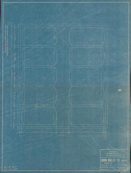
![Fermenter tanks 8'-0" wide x 15'-1" lg. x 8'-6" high : [blueprint]](/uploads/r/dalhousie-university-archives/0/c/8/0c8c0dd1855611c57fd6d6850e6aa8b61c7b582f8909244761cdccf2adf98b14/ms-4-135_os23_007_142.jpg)
![24" x 24 3/8" skimming opening for stainless steel rectangular tanks : [drawing]](/uploads/r/dalhousie-university-archives/5/7/1/57151850b37e56f544a6abb91438e3470fa4f109754c1d2e4d3a087fca705c0a/ms-4-135_os23_008_2_142.jpg)
![Cross valve piping arrangement for 10'-6" x 18'-4" horiz'l G. L. tanks : [drawing]](/uploads/r/dalhousie-university-archives/8/6/c/86c56b64ad32846b7b4b106e8e48ea9b1c946edc3b91f9b38119e2058de32d41/ms-4-135_os24_001_142.jpg)
![Pallet loader semi auto pattern arrangements : [drawing]](/uploads/r/dalhousie-university-archives/8/6/6/86618b35ce6c6243a8e646c6f1c71ca5ae1154080d7ec88c3e29bc2e0fb9c4ba/ms-4-135_os21_001_142.jpg)
![Horiz'l glass lined tanks : [blueprint]](/uploads/r/dalhousie-university-archives/7/e/7/7e752c1bdf0127f59e8bc828c7104b3fb5e81c772d0ab92071f4f1b746de2c46/ms-4-135_os24_002_1_142.jpg)
![Semi automatic pallet loader arrangement : [drawing]](/uploads/r/dalhousie-university-archives/7/0/c/70cf0112291bf52860ad615278421cc950fac95f6961b830ff8567e57ae76816/ms-4-135_os21_002_142.jpg)
![Horizontal glass lined tanks : [drawing]](/uploads/r/dalhousie-university-archives/5/f/6/5f61da6c45259fa3d2ddcae3f9cf91c5abf462f9d2a373d228ca29f70682a3f9/ms-4-135_os24_004_142.jpg)
![Horizontal glass lined tanks : [drawing]](/uploads/r/dalhousie-university-archives/d/e/3/de303f68d32f625b3c7c0c301072a5ecc960b54e649fef3be2a9c52f3da425bb/ms-4-135_os24_005_142.jpg)
![24" x 24 3/8" skimming opening for stainless steel rectangular tanks : [drawing]](/uploads/r/dalhousie-university-archives/e/9/3/e93b0fa83d4bea6d037857f4c5abb44c98dd8dc3ebedcd53038d3535e6712e5c/ms-4-135_os24_006_142.jpg)
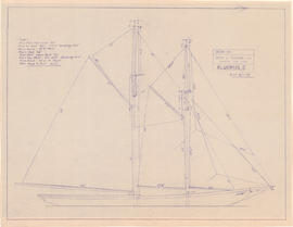


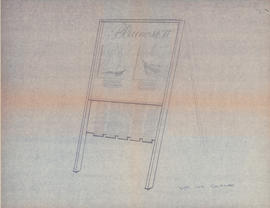

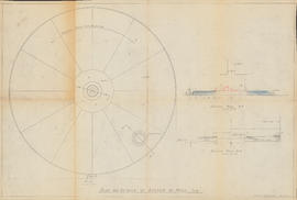
![Kioske à souvenirs pour le 'Bluenose' : [drawing]](/uploads/r/dalhousie-university-archives/a/6/1/a613c8247fc46e300554e594f43433ae5fdd21153fa8b9191493e14b4e8ef370/ms-4-135_os3_009_142.jpg)
